Hannah Stevens | Engineer. Leader. Adventurer.


Society for Advanced
Rocket
Propulsion
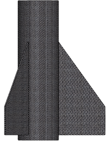
2019 Spaceport America Cup Champions
15ft Hybrid Sounding Rocket
30,000ft Target Launch Altitude
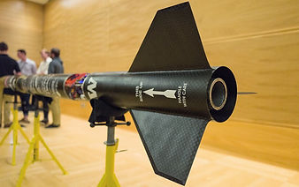
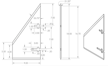
2017-2019 Structures Team
2018-2019 Fins Lead

Phase 1: Design
Purpose
Provide passive stabilization to rocket
Requirements

Force distribution on free-flying rocket
-
IREC rules: create a stability margin of 1.5 - 2 calibers
-
1 caliber = diameter of rocket
-
-
Fins not to exceed past the tail cone of the rocket
-
Enough strength to resist flutter during flight
Goals
Integration
-
Interface with injector bulkhead
-
Fits over combustion chamber
-
Radially bolted into nozzle ring
-
Aft launch lug bolts into nozzle ring
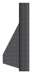


-
Manufacture fins parallel with the rocket centerline
-
Robustly attach fins
-
Reduce weight on the fin can
-
Keep drag to a minimum
-
Optimize fin geometry for greatest stability with low drag for current flight conditions
-
BETTER UNDERSTANDING OF ROCKET STABILITY!
-
Trap 1
Delta 1
Clipped Delta 1
Configurations Analyzed

Delta 2
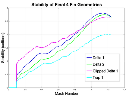


OpenRocket Configuration Simulations
Phase 2: Testing
Purpose
Confirm analysis done during design phase with another method of testing
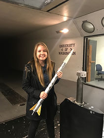
2017 SARP Wind Tunnel Model
About 3ft and too small for
KWT data resolution
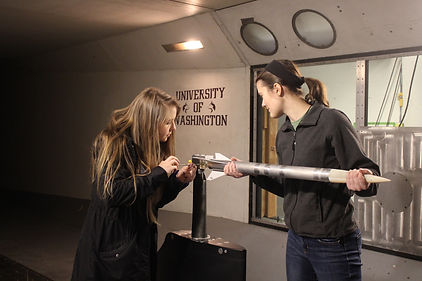
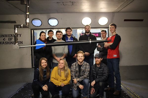
2018 SARP Wind Tunnel Model
-
6.5ft model
-
3 fin geometries
-
2 nose cones
-
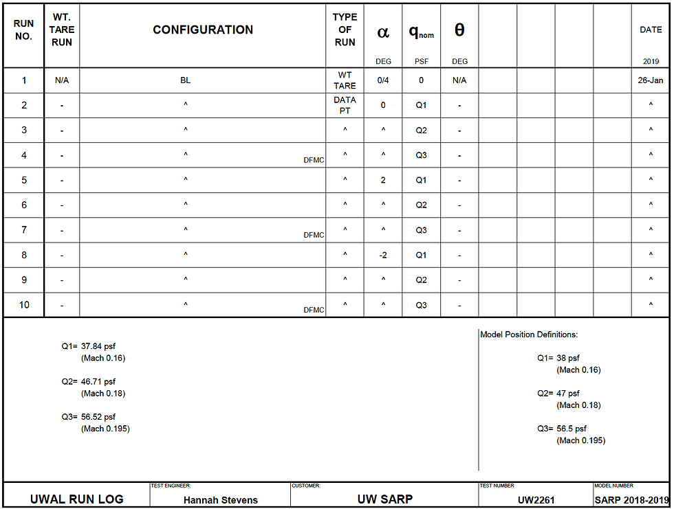
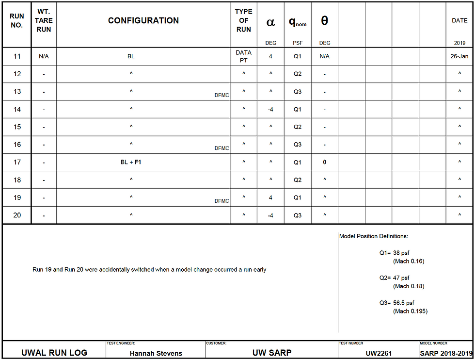
3 dynamic pressures
-
5 angles of attack
-
Internal balance
This year, there is a lot of preparation that is happening before we test:
-
Enlarging the model and moving it back in the test section
-
Lengthening the sting to limit interactions
-
Using a mini-balance with better resolution for the forces and moments of our model scale
-
Having computational data to compare wind tunnel data with BEFORE testing starts


Phase 3: Analysis
Purpose
Confirm final design for fins
Distance between CP and CG for wind tunnel model at dynamic pressure of 47 psf.

-
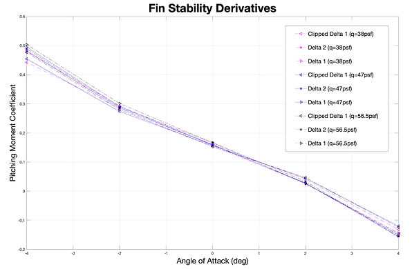
Good stability derivatives for all geometries (negative value - i.e counteracts)
-
About the same for each - clipped delta coming in slightly lower at all dynamic pressures
-
Since stability off the launch rail is the most important in determining the rocket stability during the entire flight, the fin geometry that provides the highest stability (in calibers) at the corresponding speed will be chosen
-
Off the launch rail, the rocket is traveling about 100ft/s (Mach 0.18 or dynamic pressure of 47psf)
-
The dynamic pressure the WT test was operated at
-
-
That means both OpenRocket and wind tunnel testing show Clipped Delta 1 as the best configuration.
Max Altitude (ft)
D1: 26,816
D2: 26,987
CD1: 26,042
T1: 26,581

-
Required to have at least 1.5 calibers of stability off the launch rail
-
Given the simulations we've run with the motor data from last year, we do not reach the minimum of 1.5 without completely throwing away the hope of getting close to 30,000ft
-
-
Constrained by the CG location of the overall rocket (component weights are inflexible)
-
Can only move CP back so far without extending past the tail cone/end of rocket
-
Favoring max stability over max altitude
-
Because we have experienced off-nominal flights the last two years, we elected the geometry that favors the side of stability
-
Competition flight requirements for altitude is 30% - i.e. we only have to reach at least 21,000ft to be eligible
-

The Winner:
Clipped Delta 1

Flutter analysis for Clipped Delta fin:
-
Necessary shear modulus of .179 Msi at Mach 1.3 from flutter boundary equation
-
Lower modulus ok at lower speeds
-
Carbon alone has shear modulus of .76 Msi
-
Approximate FoS of 4
Clipped Delta preformed better than the other configurations but does not produce the highest launch altitude (Delta 2 does)!
Phase 4: Manufacturing
2017-2018 Manufacturing Method
Purpose
Confirm final design for fins
Goals
-
Manufacture fins parallel with the rocket centerline
-
Robustly attach fins
-
Make at least two flight-worthy fins +fin can sets for competition
-
Prevent deformation on fin can during second cure
Method
-
Machine fin core and aluminum inserts
-
Cure fin can and all 3 fins independently
-
3 plies on each side of each fin
-
7 plies on fin can
-
Drill holes into post-cured fin can with a jig that correspond to inserts in fin
-
Bolt fins to fin can
-
Layup secondary cure
-
Unique ply geometry cut with CNC to achieve an additional 3 plies on each component (10 plies total on fin can to match the rest of airframes)
-
Vacuum bag and put in autoclave at temp lower than the glass temp of the already cured components
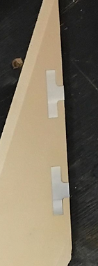


Not Circular
2018-2019 Manufacturing Method

Adding manufacturing rings to plan to prevent warping of fin can during second cure to attach assembly
Individual Fin Manufacturing
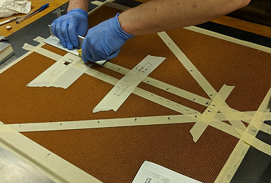
Cutting the Nomex honeycomb core to allow for fin inserts
Cutting aluminum fin inserts with water jet

Epoxied aluminum fin inserts (finserts) into honeycomb core. Drilled and tapped hole on fin inserts has been taped to prevent epoxy from filling the holes.
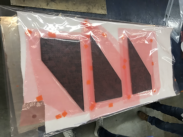
Individual fin layups prepped for the hot press. Each set includes:
-
3 plain-weave plies (0º, 45º, 0º)
-
Adhesive film
-
Core with fin inserts
-
Adhesive film
-
3 plain-weave plies (0º, 45º, 0º)
Water jetting the fins to expose the inserts and bolt holes for attaching to fin can
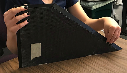
Epoxying 3D printed wedged edges to fin base
Fin Can Manufacturing

Using mandrel to create fin can to ensure same diameter as rest of rocket air frames
Fin Assembly Manufacturing
Using fabric cutter to create precise, repeatable sheets of carbon fiber plain-weave and adhesive film for layups

Attaching adhesive film to fin assembly. Fin assembly includes already individually cured fins and fin can
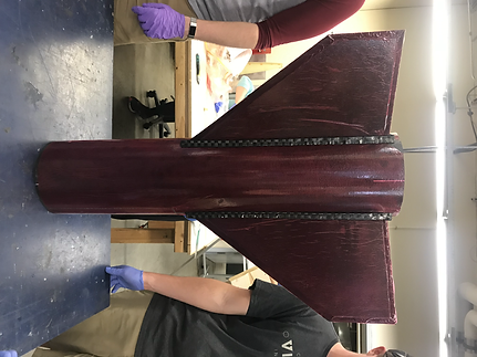
Layer of adhesive film with carbon fiber plain-weave folded accordion-style to create fillet at fin-fin can interface
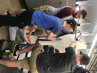

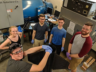
All hands on deck for carbon fiber ply application. 3 layers of carbon fiber plies are laid up (0º, 45º, 0º).
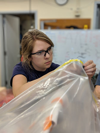
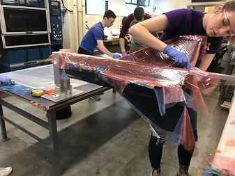
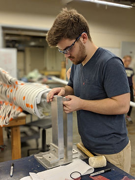

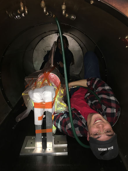
Prepping fin assembly for second cure. Applying release film to carbon to prevent adhesion to breather and bag. Applying breather to create even pressure on assembly and pathway for resin to seep. Bagging and sealing to hold ~29psi
under vacuum for 5 minutes before placing in autoclave and baking twice!
Phase 5: Assembly
Purpose
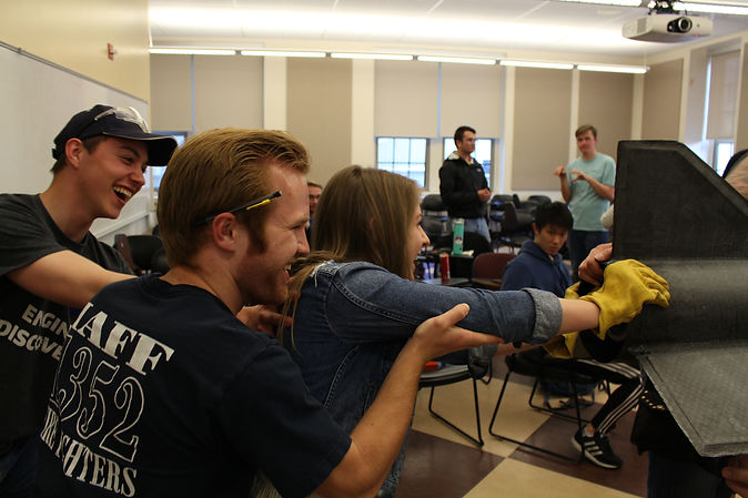
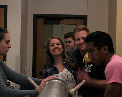
Assembly and integration checks before competition
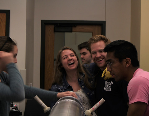


Phase 6: Competition
Purpose
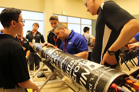
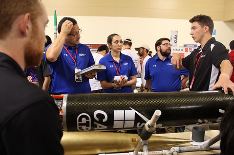
Driving down to Spaceport America in Las Cruses, NM with the rocket in tow. Sharing at the convention day for judges and other teams.

Answering questions for judges about system and design choices.
Phase 7: Launch Day
Purpose

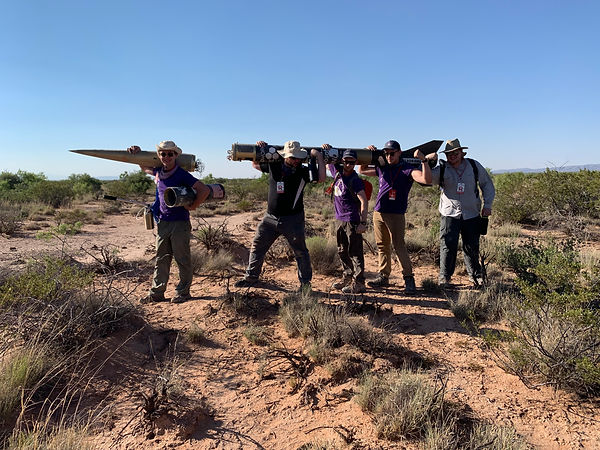
"Clear range, clear skies!" it's time to launch!


2 days.
1700 miles.
Rocket recovered and fins survived landing and being dragged a mile across the desert because of the parachute (yay - fin strength!)
Phase 8: Results

1st Place: 30,000ft SRAD Hybrid
SRAD:
Student Researched and Designed

Judge's Choice and Overall Winner